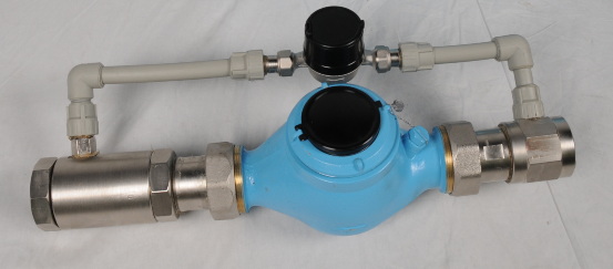
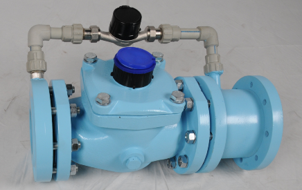
Combined water meter nodes
Designation: The combined water meters are designed to measure water consumption over a wide flow range. In this way the large flow of the water flow rate is taken by the main water meter, and at the low flow rate the additional water meter is used. The reading of the additional water meter is much more precise and this is an important moment when we have a low flow rate in the system
The combined water meter with flange connection is designed to measure water flow at a temperature not higher than 50°C. The water meters are mounted horizontally, with the clock mechanisms on top.
Implementation options:
• CWM 20/3 measuring range of 0.050 m³/h, up to 20 m³/h, threaded connection
• CWM 30/ЗF* measuring range of 0.050 mЗ/h up to 30 mЗ/h, threaded and flange connection
• CWM 30/5F* measuring range of 0.080 mЗ/h up to 30 mЗ/h, threaded and flange connection
• CWM 50/5F measuring range of 0.080 mЗ/h up to 50 mЗ/h, flange connection
• CWM 80/5F measuring range of 0.080 mЗ/h up to 80 mЗ/h, flange connection
• CWM 125/5F measuring range of 0.080 mЗ/h up to 125 mЗ/h, flange connection
• CWM 125/7F measuring range of 0.126 mЗ/h up to 125 mЗ/h, flange connection
Combined water meters are also available with remote reading.
Advantages:
• option of autonomous checking of each of the two water meters
• easy disassembly during repair
• dry, easy to read clock mechanism
• function against reverse flow
• option of equipping already installed water meters
Metrological characteristics – Combined water meters nodes
|
|
|
|
КВВ20/3 |
КВВ30/3 (Ф*)КВВ30/5 (Ф*) |
КВВ 50/5Ф |
КВВ 80/5Ф |
КВВ125/5ФКВВ125/7Ф |
|
Nominal diameter |
DN |
mm |
40/15 |
50/15 50/20 |
65/20 |
80/20 |
100/20 100/32 |
|
Permanent flowrate |
Q3 |
m3/h |
16 |
25 |
40 |
63 |
100 |
|
Permanent flowrate of the additional water meter |
Q3 |
m3/h |
2,5 |
2,5 4 |
4 |
4 |
4 6,3 |
|
Overload flowrate
|
Q4 |
m3/h |
20 |
31,25 |
50 |
78,75 |
125 |
|
Minimum flowrate |
Q1 |
m3/h |
0,050 |
0,050 0,080 |
0,080 |
0,080 |
0,080 0,126 |
|
Transitional flowrate |
Q2 |
m3/h |
0,080 |
0,080 0,128 |
0,128 |
0,128 |
0,128 0,201 |
|
Switching
|
|
m3/h |
0,320 |
0,500 |
0,800 |
1,200 |
2 |
|
Connection
|
|
|
1 ½” |
2” / Фланци * |
Фланци |
Фланци |
Фланци |
|
Temperature klasse |
Т |
оС |
50 |
50 |
50 |
50 |
50 |
|
Pressure MAP
|
PN |
bar |
10 |
10 |
10 |
10 |
10 |
|
Installation
|
|
|
horizontal |
horizontal |
horizontal |
horizontal |
horizontal |
|
Length
|
L |
mm |
650 |
650 / 480* |
480 |
530 |
530 |
|
Weight
|
G |
kg |
10 |
13 / 39* |
39 |
56 |
56 |
2019-07-15 11:58:23 UTC